- Alternating Current:-
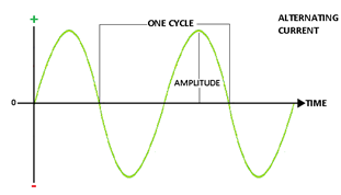 An alternating current (a.c.) is a current which continuously, changes in magnitude and periodically reverses in direction.`
i = I0 sin ωt = I0 sin (2π/T) t
Here I0 is the peak value of a.c.
(a) Current, I =I0 sin ωt
(b) Angular frequency, ω= 2πn (n is the frequency of a.c.)
(c) I =I0 sin 2πnt
- Mean value of A.C or D.C. value of A.C.:-
Mean value of a.c. is that value of steady current which sends the same amount of charge, through a circuit, in same time as is done by a.c. in one half-cycle.
(Iav)half cycle = (2/π)I0
Thus, mean value of alternating current is 2/π times (0.637 times) its peak value.
(Vav)half cycle = (2/π) V0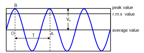

- Average value of A.C. over a complete cycle:-
Iav = 0
The average value of a.c. taken over the complete cycle of a.c.is zero.
- Root mean square value of a.c. or virtual value of a.c.:-
Root mean square value of alternating current is defined as that value of steady current which produces same heating effect, in a resistance, in a certain time as is produced by the alternating current in same resistance in same time. The r.m.s value of a.c.is also called its virtual value.
Irms = I0/√2
Root mean square value of alternating current is I/√2 times (or 0.707 times) the peak value of current.
Similarly, Vrms= V0/√2
Here V0 is the peak value of e.m.f.
- Form Factor:-
Form Factor = rms value/average value = (V0/√2)/ (2 V0/π) = π/2√2
- Current elements:-
(a) Inductive reactance:- XL = ωL
Here, ω = 2πn, n being frequency of a.c.
L is the coefficient of self-inductance of coil.
(b) Capacitative reactance:- Xc = 1/ωC
Here C is the capacity of the condenser
- Capacitor in AC circuit:-
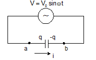 q = CV0sinωt
I = I0 sin(ωt +π/2)
V0 = I0/ωC
Xc = 1/ωC
- Inductor in AC circuit:-
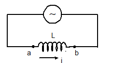 VL = L(dI/dt) = LI0ω cosωt
I = (V0/ ωL) sinωt
Here, I0 = V0/ ωL
XL = ωL
And the maximum current, I0 = V0/XL
- R-L circuit:-
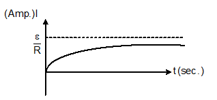
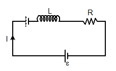 I = ε/R [1-e-Rt/L]
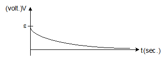
V = ε e-Rt/L
- Graph between I (amp) and t (sec):-
- Graph between potential difference across inductor and time:-
- L-C Circuit:-
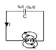 f = 1/2π√LC
q = q0 sin (ωt+ϕ)
I = q0ωsin (ωt+ϕ)
ω = 1/√LC
- The total energy of the system remains conserved,½ CV2 + ½ Li2 = constant = ½ CV02 = ½ Li02
- Series in C-R circuit:-
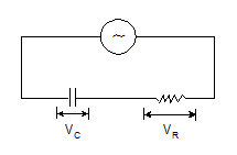
V = IZ
The modulus of impedance, |Z |= √R2+(1/ωC)2
The potential difference lags the current by an angle, ϕ = tan-1(1/ωCR)
- Series in L-C-R Circuit:

V = IZ
The modulus of impedance, |Z |= √[R2+(ωL-1/ωC)2]
The potential difference lags the current by an angle, ϕ = tan-1[ωL -1/ωC)/R]
- Circuit elements with A.C:-
Circuit elements
|
Amplitude relation
|
Circuit quantity
|
Phase of V
|
Resistor
|
V0 = i0R
|
R
|
In phase with i
|
Capacitor
|
V0 = i0XC
|
C
|
Lags i by 90°
|
Inductor
|
V0 = i0XL
|
XL = wL
|
Leads i by 90°
|
- Resonance:-
(a) Resonance frequency:- fr = 1/2π√LC
(b) At resonance, XL = XC, ϕ = 0, Z = R(minimum), cosϕ = 1, sinϕ = 0 nad current is maximum (=E0/R)
- Half power frequencies:-
(a) Lower, f1 = fr – R/4πL or ω1 = ωr – R/2L
(b) Upper, f2 = fr + R/4πL or ω2 = ωr + R/2L
- Band width:- Δf = R/2πL or Δf = R/L
- Quality Factor:-
(a) Q = ωr/Δω = ωrL/R
(b) As ω = 1/√LC, So Q ∝ √L, Q ∝1/R and Q ∝ 1/√C
(c) Q = 1/ωrCR
(d) Q = XL/R or Q = XC/R
(e) Q = fr/Δf
- At resonance, peak voltages are:-
(a) (VL)res = e0Q
(b) (VC)res = e0Q
(c) (VR)res = e0
- Conductance, susceptance and admittance:-
(a) Conductance, G = 1/R
(b) Susceptance, S = 1/X
(c) SL = 1/XL and SC = 1/XC = ωC
(d) Admittance, Y = 1/Z
(e) Impedance add in series while add in parallel
- Power in AC circuits:-
Circuit containing pure resistance:- Pav = (E0/√2)×(I0/√2) = Ev×Iv
Here Ev and Iv are the virtual values of e.m.f and the current respectively.
Circuit containing impedance (a combination of R,L and C):-
Pav = (E0/√2)×(I0/√2) cosϕ = (Ev×Iv) cosϕ
Here cosϕ is the power factor.
(a) Circuit containing pure resistance, Pav = EvIv
(b) Circuit containing pure inductance, Pav = 0
(c) Circuit containing pure capacitance, Pav = 0
(d) Circuit containing resistance and inductance,
Z = √R2+(ωL)
cosϕ = R/Z = R/[√{R2+(ωL)2}]
(e) Circuit containing resistance and capacitance:-
Z = √R2+(1/ωC)2
cosϕ = R/Z = R/[√{R2+(1/ωC)2}]
(f) Power factor, cosϕ = Real power/Virtual power = Pav/ErmsIrms
- Transformer:-
(a) Cp = Np (dϕ/dt) and es = Ns (dϕ/dt)
(b) ep/es = Np/Ns
(c) As, epIp = esIs, Thus, Is/Ip = ep/es = Np/Ns
(d) Step down:- es < ep, Ns< Np and Is> Ip
(e) Step up:- es >ep, Ns>Np and Is< Ip
(f) Efficiency, η = es Is/ ep Ip
- AC Generator:-
e = e0 sin (2πft)
Here, e0 = NBAω
0 comments:
Post a Comment